* Engine rebuild
* Exhaust design
* Ignition coil replacement
* Coil upgrade
* Ignition timing
* Repair of broken air cleaner lever
* Alternative piston options
* Crankshaft drawing MB250
* Bearing & seal numbers MB250
* MB250 Wiring diagram
* Oil in fuel. Synthetic OR mineral ?
* Adler information compiled by Australian owners
If you would like to make a comment on any article on this page please forward to my email ( see the Home page ).
New articles are always welcome.
The aim of the web site is to provide information & help in the restoration & running of the Adler.
Engine rebuild
Details provided by Rowan Bond in Australia.
If your Adler Big ends and con rods are unserviceable, you can try and get new ones from someone in Germany (good luck), or you can stroll down to your local bike shop and try this:-
Kawasaki A1 Samuri con rods are almost exactly the same length ( slight increase in compression ).
The big end pins need to be reduced from 20 mm to 17 mm to fit the Adler flywheels.
If you are going to grind down the ends to make a double diameter pin, USE EXTREME CAUTION that there is sufficient radius or else they will break (as mine did).
The Adler Crankpins are actually 2 piece, so press off the sleeve from the crankpin and have the Kawasaki pin cut and bored to 17mm hole through the centre.
Press this sleeve onto the original adler crankpin, and it works perfectly.
You can actually get 2 sleeves from one Kawa pin, which is good as the pins are quite expensive.
Note that the standard Adler big end crank pin has a central diameter of 22.39 mm with 17 mm to fit the Adler flywheels.
The 22.39 mm crank pin is used with the roller cage ( 12x5 mmx8 mm rollers ) to fit the standard Adler con rod big end of 32.39 mm.
If your pistons are too worn, obtain a set of Suzuki GT250 pistons and rings which are perfect except for a very slight loss of compression ( see con rod length ).
Combination of piston and kawasaki rod brings compression back to original.
You have to relieve some metal from the bottom of the piston where the transfer cutouts are to clear the flywheels.
Standard suzuki gudgeon pins are OK but with the Kawasaki needle roller small end bearings.
Take caution that you order Suzuki pistons that are earlier than 1976, as they have 16mm gudgeons which compliment the Kawasaki con rods but 1976 onward have 14mm pins.
There are no available needle bearings to suit this combination but I made up bronze bushes for the little ends and have had no problems at all in 13 years of riding.
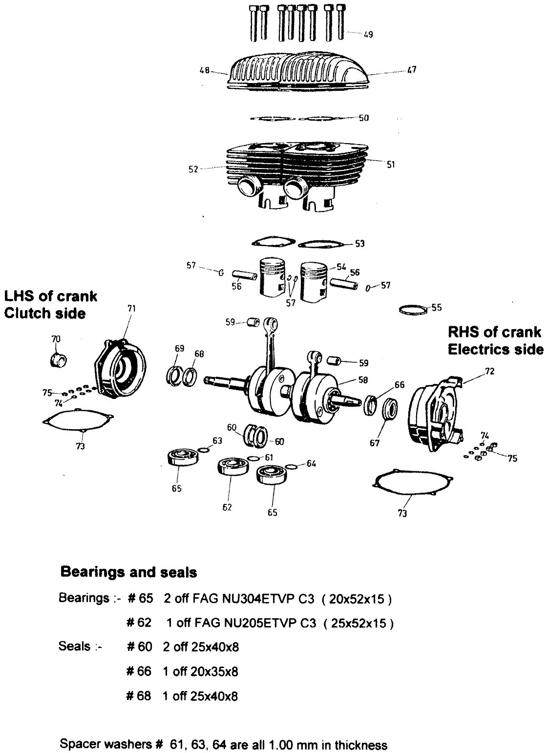
Modern bearing and seal sizes for the crankshaft are:-
2 of Fag No NU304ETVP C3 tolerance ( 20x52x15 )
1 of Fag No NU205ETVP C3 tolerance ( 25x52x15 )
It is important to specify C3 tolerance.
I used standard tolerance originally, but the crank started tightening and squeaking (literally).
After a tear down, the local FAG agent was kind enough to send the bearings away for testing as they appeared perfect.
The results were that C3 ( slightly looser tolerance 30 micron I believe ), should have been used, as the Adler crankcases hold the shaft and bearings very tightly ( being exquisitely made ) and allowed no room for expansion when heated.
The outcome was that the bearings started to tighten upon themselves.
So C3 it is.
Seals for the crank are 3 of 25x40x8 p/n PR8094 and 1 of 20x35x8 p/n not known.
I did have problems sourcing the seals for the kickstart and gear selector shaft which are 17x27x7 and also the fork seals which are 22x32x7.
They are available but you have to keep on the bearing suppliers back to track them down. I would suggest you buy a couple of each extra to be on the safe side and put them aside. they are very cheap.
HINT, When you pass the left hand crank shaft through the centre bearing and seals make up a gadget to lead the crank through the seals ( wood or metal shaft ) with a spigot to go into the threaded section and the outside diameter slightly larger than the inside diameter of the seal or the Hirth coupling teeth will tear your seals sto shreds.
Unfortunately the first you will know about it is then the bike is attempted to be started and crankcase compression will be grossly effected. the bike probably will not go, and will necessitate a teardown to replace the seals.
Exhaust design
A drawing of the exhaust system was provided by the Adler factory in 1955 to John Wynne in Australia, as a racing car using a Adler motor was being developed.
The exhaust was the latest development from the Adler factory and was used on the 250 RS bike.
The Adler motor had been installed in the racing car and different exhaust systems from megaphones, reverse cones and varying lengths of straight pipes were used in an attempt to achieve the greatest potential from the motor.
The exhaust design provided by Adler, gave a huge increase in HP with the car winning its first hill climb outing.
Different outlet diameters ( using plugs at the end of the pipe ) , were tried with the following results :-
32 mm for road racing with power band between 6000 - 12000 rpm .
18 mm for sprints with power band 4000 - 10000 rpm
15 mm for hill climbs with power coming in at 2000 rpm .
With modified ports and heads , the motor produced 36 HP with maximum revs of 12000 with 14:1 compression , running on methanol and achieved a top speed of 120 mph.
The motor was further modified by the use of pistons and special rings manufactured especially for the car by Repco in Australia.
Repco were associated with the construction of the Climax engine used by Jack Brabham , the Australian Formula 1 racing car world champion .
John Wynne the builder of the car, is now retired to the Gold Coast in Australia but the Adler powered car still resides in his garage.
John was a friend of Phil Irving ( Vincent motorcycle fame ) and collaborated on the articles in Phil`s books " Tuning for speed " and " Automobile engine tuning "
The drawing of the exhaust system is available on request.
See the Adler Information page.
Details of the race car are on the Other Adler Sites page.
Ignition coil replacement
Details provided by Rowan Bond in Australia
In the interests of very neat and smooth appearance, Adler motorcycles had their ignition and charging system hidden behind the right hand side cover of the engine.
The only external signs of the system were the two high tension wires appearing from a rubber grommet on the top right of the crank cases adjacent to the carby.
There is no argument that this made for a neat looking bike but almost 50 years down the track it causes major reliability problems with the model.
Ignition and charging systems would rather be running in a cool place preferably in the airstream.
Being hidden under the cover exposes the electrical system to dual problems being both out of the airstream and also having to contend with actual engine temperature at all times. No wonder they fail.
Firstly the charging system. The original Bosch regulator is sited at the front of the ignition setup of the motorcycle under the right cover.
I have seen several that work properly, but a combination of age and heat render them useless.
The regulator appears to be identical to one fitted to BMWs of the era, so a source of parts may be found. I didn't like the placement of the regulator, so when mine failed, I sited a standard (cheap) VW type regulator under the dual seat.
The wires were run from the harness in the battery box to the regulator neatly and hidden. I have had no troubles since fitting this regulator, and the instruction sheet that came with the regulator was easy to follow to wire up.
Remember that the Adler is a battery coil ignition system so that a working charging system is critical to the reliability of the motorcycle.
Coil replacement. The coils failed shortly after this modification and that presented much more problems. I removed the coils and had them tested.
The auto electrician deemed them dead, and I did not have a clue where to source parts (This was 12 years ago).
I wasn't sure I wanted to source the original parts anyway as it was only a matter of time before they would have failed as well.
Cost of rewinding the coils was prohibitive, and then they would be back in the same hot place to cause problems once more.
Having looked around, I found a couple of neat coils off a Honda CB100 which were black, would fit under the tank and easily mounted off a fabricated bracket attached above the front tank mount.
Having fabricated the bracket in 3mm plate, I mounted the coils in the gap between the front tank mount and inside the valley of the tank (They are totally out of sight ).
The coils are mounted one behind the other on the twin frame rails.
Ensure the coils are well earthed. Wiring was accomplished, by removing the old coils, and adding quality connectors to the existing wires from the condensor and power wire to the old coil.
This makes a total of 4 wires (make sure you use different colours to aid identification under the tank), which were routed back through the wiring hole in the crankcase under the carb cover.
After liberal coatings of rubber grease, the 4 wires were slid into about 1 metre of black 7mm rubber tube which was then routed under the carb, through the drain in the front of the crank cases between the cylinders, under the front crankcase fins and up the left front downtube adjacent to the clutch cable.
The new wiring hardly shows on my black frame.
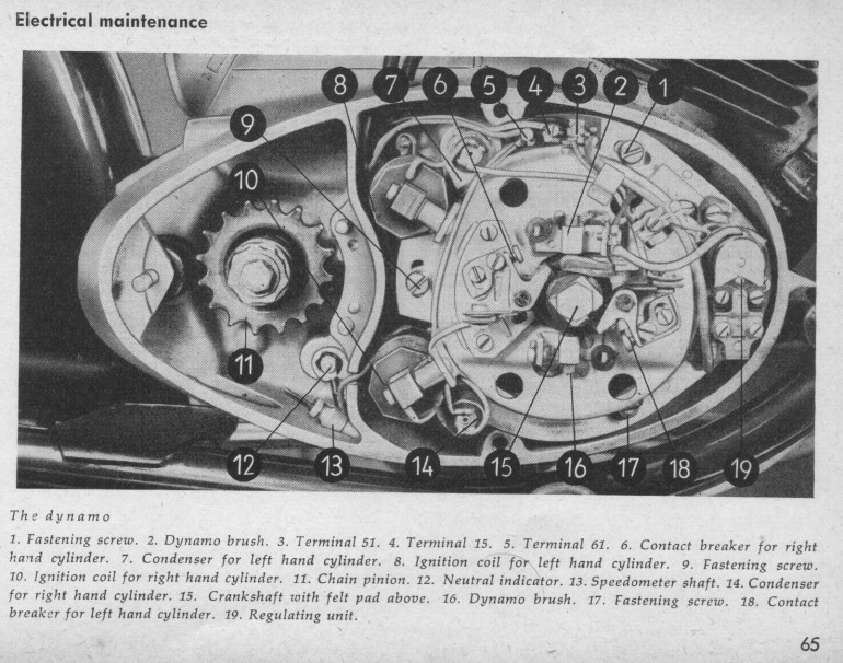
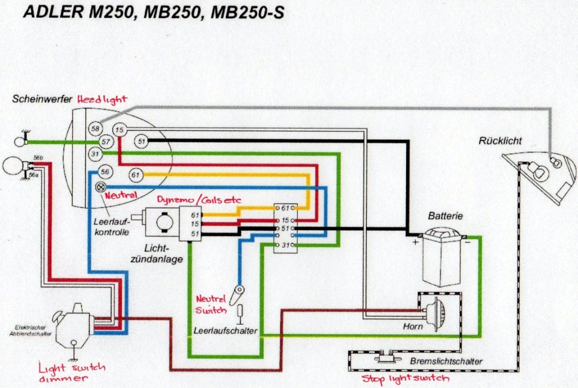
Wiring detail from the original owners manual is included for your information.
Once the wiring is drawn up the frame, it is an easy matter to wire the new coils the same as they were originally wired for the Honda.
It is critical to ensure you have 6 volt coils for a battery coil ignition system as the majority of Japanese trail bike coils are either magneto or CDI ignition coils which WILL NOT WORK on the Adler wiring.
Honda CB100, XL100, XL125, CB125, XL175 (K1 model only) etc of the mid 70s work fine and are readily available at wreckers.
Yamaha also make some lovely battery coil systems but are much rarer.
Suzuki and Kawasaki went to CDI arrangements very early in the piece and are therefore not much use for this application.
The high tension leads now appear from under the tank and not out of the right side of the engine, and a suitable rubber grommet was found to plug up the hole in the top of the crankcase.
I considered making up dummy HT leads to look original, however Adlers are so rare, no-one has picked up the modifications in 14 years.
I guess the 4 wires could be added to the existing wiring harness and exit under the tank instead of going up the front of the bike frame, but this is how I did it.
The ignition system has not given me any problems whatsoever since the mods were carried out, and all trace of misfiring and poor hot starting disappeared immediately Happy motorcycling.
Click to enlarge
Coil upgrade ( alternative method )
Further information on coil replacement by Don Littleford.
The Adler` coils are mounted inside the right hand engine cover and are subjected to heat and tend to fail as they get old.
I was trying to keep my bike as original as possible and had my original coils rewound after they failed.
Epoxy was used but this is not a cheap option.
However the rewound coils worked well although they were still mounted inside the motor.
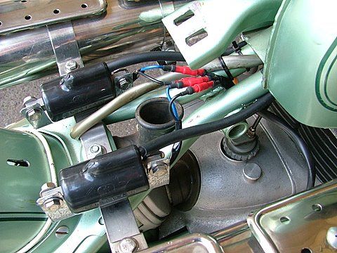
I had previously converted my MB 250 to upswept exhausts so there was a convenient mounting point under the seat for the coils.
The conversion to upswept exhausts required the removal of the " saddle spring cover plate ", Part 358 in the Adler spare parts list.
The first thing to do was to find suitable 6 volt coils.
Several models had been recommended so I went searching at motorcycle shops and bike wreckers.
I found modern coils sold in Australia by MCS.
They supply to most distributors / wreckers but if you cant find a agent, contact them direct at 07 3375 6600, mobile 0427 013 256 .
The coils are manufactured in Taiwan and are used extensively for battery, coil, points system.
The 6 volt coils in their catalogue are part number CH4 ( CB 100 K4).
There are other coil options and another owner advised his bike is using external Bosh TL3/1 coils.
The Taiwanese coils are shown in the photo. Stamped FL 801-6V.
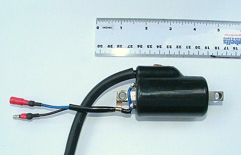
It is important that coils for battery coil points ignition are used as others ( CDI ) will not work on the Adler system.
You therefore need a coil with three leads. Power in, power out to condenser / points, and a spark plug high tension lead.
I had to change the connectors as I could not find ones to match those on the coils.
The CH4 coils were not marked with + or - , although I was told by the supplier that the black wire with the male connector was to be used for power in.
This makes sense, as it would mean that the power wire from the battery would have a female connection and would be safer if ever the connection came apart, there would not be a live wire to short out on the body.
With the -ve earth Adler it is essential that the +ve battery connection goes to the +ve connection on the coil.
If there is any doubt as to the performance of the existing condensers mounted adjacent to the existing coils inside the motor they should also be replaced.
It is recommended that the existing condensers also be replaced.
These can be located beside the new coils in the air flow.
6V condensers can be easily obtained from a auto electrical shop
Mounting of the coils under the seat in my case was relatively simple by manufacturing light brackets ( refer photo ), while making sure the coils were earthed well.
If mounting under the seat, make sure that the seat will be clear of the coils when installed.
I used heat shrink on all connections to make them secure, and 5 core flex ( used for trailer wiring ) , as I was still going to use the existing high tension leads hole in the engine case to access the internal points.
Needing only 4 wires I just cut off the unwanted one.
Before the new wiring was connected I isolated the existing coils in the motor.
This involved removing the high tension leads and the connections between the coils and the condensers.
As I was going to used the existing condensers , the wires between the condensers and the points remained.
If the condensers are old they should also be replaced.
I wanted to keep the existing coils in place as they were still working and would be available if any future owner of the bike wanted to go back to the original wiring.
It would be a simple process to rewire the coils back into the system.
The wiring inside the motor is as follows, you can refer to the image ( click for full size ) for more detail :-
- Connect the four wires to coils and feed them through the grommet to be used to seal the case.
- Disconnect the power wire from the backing plate ( terminal 5 in diagram ) and connect to the two black power wires to the coils. Don`t use the existing screw attachment as this will mean power remaining to the existing coils. I just joined the three wires and tucked them into the space behind the backing plate.
- Connect the remaining two blue wires to the existing condensers, making sure you match up the wire from the left coil to the left cylinder condenser ( left to 7 and right to 14 in the diagram ).
- Connect the high tension leads to the plugs. I used plug caps that just screwed into the high tension leads .
That`s all there is to it.
The bike should start and the coils will no longer be affected by heat .
Ignition timing. A simple but relatively accurate method
Equipment needed :-
- T section of dowel to measure depth of piston ( depth indicator with handle ) .
Leg that goes into the plug hole being approximately 70 mm. See comment below
- Timing disc socket made out of plastic protractor glued to 14 mm socket
( you don`t have to remove the 14 mm bolt holding the electrics on ) .
- 6 v test light to go across points .
- Pointer which is attached to the motor case using an existing bolt hole and that can be bent so that it will be close to the timing disc edge .
- Wire or light metal is adequate.
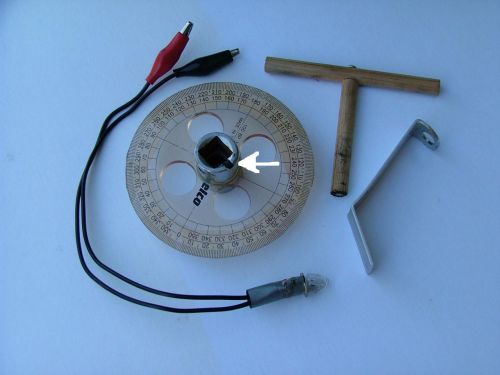
Photo 1
Procedure :-
Remove spark plugs from both cylinders .
Adjust contact points gap for each cylinder . ( 0.3 - 0.4 mm ) . ( see note below ).
To time left cylinder .
Put dowel depth indicator down the plug hole .
Hold handle of T firmly against the cooling fins on the head and turn the motor over with a spanner on the bolt head until the piston touches the dowel .
Piston can be rocked back and forth with the spanner to get an accurate position as you can feel the piston when it touches the dowel .
The disc socket and the bolt head have a mark so that the disc socket is always put on the bolt head at the same location . ( see photo`s 1 & 2 ) .
Put the timing disc socket onto the bolt head and take a degree measurement against the pointer. Record this degree `A` .
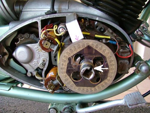
Photo 2
Take into account for any free play between the disc socket and the bolt head by turning the disc socket clockwise against the bolt head with a little pressure ( make sure you don`t rotate the motor ) , before taking the degree measurement .
Do this before taking any readings .
If the disc socket fits snugly with no free play then there is no need for this
The 70mm depth will give a location of the piston approx 30 degrees before TDC.
A shorter depth gauge than 70mm OR a dial gauge, will give a more accurate reading.
For greater accuracy, use a spark plug with the internals removed.
Make a hole down the centre of the spark plug slightly larger than the dowel diameter.
Screw the spark plug into the head,
The dowel will then go down the centre of the spark plug & sit on the same position of the piston.
Remove the disc socket and rotate the motor as before to go past TDC .
The dowel depth indicator rises out of the cylinder and then drops again .
When the handle of the T sits on the fins again take another degree measurement with the disc socket .
This gives the same position of the piston after TDC . ( approx 30 degrees as before ).
Make sure the disc socket goes on the bolt at the same position .
Record degree `B` .
The difference between the two degree readings A & B on the disc gives a degree reading for TDC .
Make a note of this reading `C` .
Work out the degree reading you need on the disc for correct timing before TDC .
( MB 250 is 22 degrees before TDC ) . Reading `D` .
Rotate the motor by turning the timing disc so that it reads the correct degrees before TDC
The piston in the left cylinder in now set at the correct position before TDC .
It is this location that the ignition points should be just opening .
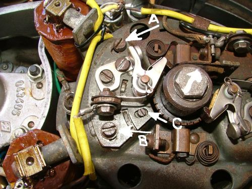
Photo 3
Loosen the three adjusting screws holding the backing plate to the engine body .
The screws should be loosened just enough to let the backing plate move .
If the backing plate is too loose the plate will rock and alter the points gap .
Without moving the piston from this position install the test lamp across the points for the left cylinder and turn the ignition on .
When adjusting the motor with the ignition on it is best to short the high tension leads out against the body so as to release the spark built up in the coils .
Adjust timing by rotating the backing plate to get the points to open at this position of the piston.
The test light comes on when the points just open .
Tighten up the screws holding the backing plate to the motor and recheck.
The left cylinder is now timed .
If you cant get the points to open with the backing plate fully rotated against the stop, then open the points a little bit more than the 0.4 mm as specified.
This problem is the result of normal wear in the system
Do the same with right cylinder but make the timing adjustments by moving the right cylinder points where they are mounted onto the backing plate and not by rotating the backing plate .
This would change the set up for the left cylinder .
See photo 3 .
Undo screws A and B and adjust with cam screw C .
It is important that small brass washers be placed under screws A and B .
Otherwise when tightening up these screws the small plate tends to move against the backing plate and the timing will be wrong.
The motor should be run and the timing rechecked .
Depending on the condition and wear in the motor , the timing should not have changed .
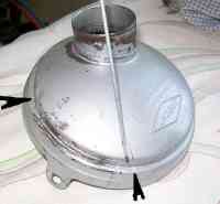
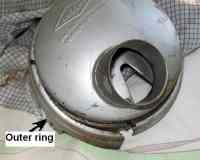
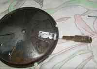
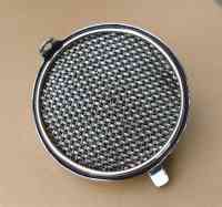
Repair of broken air cleaner lever
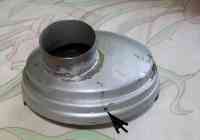 |
Drill a small hole in the outer ring of the air cleaner
( indicated by arrow ).
A self tapping screw will be used to realign the outer ring with the main air cleaner body and the offset carburetor air inlet tube when re-assembling the air cleaner ( photo 13 ). |
 |
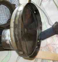
Drill out the 4 spot welds which hold the outer ring to the air cleaner body.
Photo 4 shows that the drill holes go through the air adjusting vents.
|
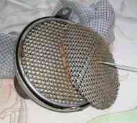 |
Remove the filter meshes using a hook wire puller. |
 |
Remove the seal which may have to be replaced if damaged.
|
 |
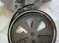
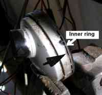
The outer ring should come apart from the air cleaner body.
If not, the outer ring needs to be cut and pried apart
( arrow photo 5 & photo 6 ). |
 |
|
 |
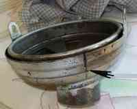
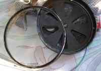
After removing the outer ring the air cleaner body needs to be cut with a thin blade all the way around to remove the inner ring.
A thin cut is necessary as the inner ring will be soldered back in place and there has to be sufficient space for the filter meshes.
The inner ring and main body can be marked so the inner ring is put back in the same position. |
 |
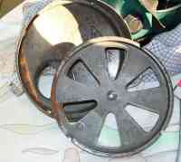
The inner ring removed showing the air adjusting vents which can be removed.
The vents were held in place by the 4 spot welds which have been drilled out. |
 |
|
 |
A new lever is made from 1 mm brass and silver soldered over the top of broken lever. |
 |
The vents are replaced inside the main filter body and the fixed vent is spot soldered into place.
Make sure the lever is in the correct position and the adjustable vent moves freely for the full length of the slot.
The inner ring is soldered back ( right around ) and the mesh filters replaced.
|
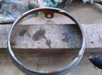 |
Adjust the diameter of the outer ring to fit over the air cleaner body, solder together at the cut ( photo 5 )
and repair the drill holes in the outer ring.
Align the filter and insert a self tapping screw.. |
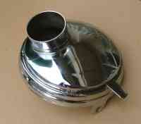 |
Final filter assembly
Parts of the filter can be chrome plated before assembly.
Chrome the lever only and not the vents. |
 |
|
Alternative piston options
When restoring the Adler motor, there is a problem in that the original pistons are rare and difficult to find.
There are other options and some other brand pistons are readily available.
What we need is a piston that is as close as possible to the dimensions of the original.
The original Adler pistons for a standard 54.0 mm bore are :-
Adler YD3
Total length ( incl dome ) 70.0 mm 69.9 mm
Dome 3.0 mm 3.0 mm
Gudgeon pin diameter 15.0 mm 15.0 mm
Distance from centre of gudgeon pin to lip of piston 30.0 mm 30.1 mm
Diameter for standard piston 53.96 mm
Weight ( piston only ) 175.0 grams 170.0 grams
Note :- If using the YD3 pistons the clearance between the bottom of the piston & the flywheel should be checked.
It may be necessary to trim a small section off the skirt of the piston.
Pistons with almost the same dimensions of the original Adler are :-
Mahle:- Available from Motorrad Stemler in Germany, weight 165.0 grams
Yamaha YD3:- Available on E Bay. YD3 bike in early 1970's, weight 170 grams
Yamaha DS7:- Rarer with 16 mm pin and lighter at 145 grams
These piston sizes start at 53.96 mm and increase in diameters by 0.25 mm.
The dimensions of the readily available YD3, 2 ring piston are shown in red above.
The 53.96mm Yamaha YD3 standard numbers are :-
Piston 148-11631-00-96
Rings 148-11610-00
Gudgeon 148-11633-00-00
Other options include the Suzuki GT250X7.
However these are 5.5 mm shorter, 10.0 grams lighter and have a 14 mm pin.
While the lighter weight is not a problem, as the flwheels / conrod / piston are usually balanced during assembly, the shorter length does affect port timing.
This results in the power comes in at higher revolutions of the motor and therefore affects low down accelleration, hill climbing etc.
Crankshaft drawing
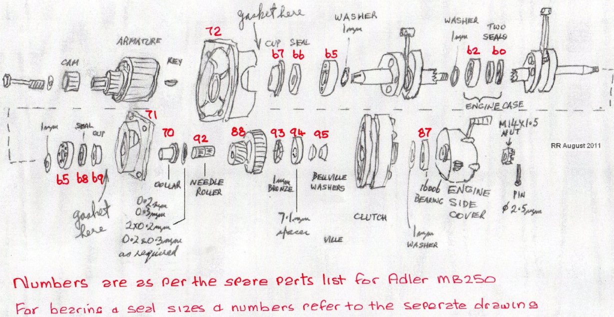
Bearing & seal numbers MB250
It is important that only C3 tolerance bearings be used
MB250 wiring diagram
Oil in fuel. Synthetic OR mineral ?
There is much debate as to the petrol / oil mix to use in the Adler.
If you talk to owners, a few use synthetic oils at high mix rates of 1 : 40, while others use mineral oil at 1 : 25.
It must be remembered that when the Adler came on the market in the 50's, that only mineral oil was available and Adler recommended mix rates of 1 : 25.
Since that time the quality of oils has improved and if using mineral oil then 1 : 30 could be suitable.
There will always be a discussion as to what oil you should use initially after a engine rebuild.
For the first 500 km a mineral OR semi synthetic ( mix of mineral & synthetic ) could be the best option to bed in the rings & bore.
Followed by a full synthetic oil.
There has been a lot of research on the internet as to the best option for vintage bikes.
When you make your decision talk to other Adler owners to get their opinion.
Adler information compiled by Australian owners
The Australian owners over the years have compiled a lot of information on the Adler.
This has been incorporated into a CD disc
For example this link provides a indication of what is on the disc.
http://www.historicmotorcycle.org.au/Adler/
Contents include :- Workshop handbook, Owners handbook, Part suppliers, etc.
The information contained in the CD is freely available
|